Welcome: ZHUOHE INSTRUMENTATION CO.,LTD


The Design of the Small Automatic Batching Machine Control System
By Sui Tao, Li Bing, Liu Xiuzhi, Xu Wenshang
College of Information and Electrical Engineering of Shandong University of Science and Technology
Qingdao, China
Abstract-The paper describes a small batching machine control system that takes chip C8051F040 as the core controller. The system that has automatic control and manual control modes can complete the high-precision automatic weighing of few powder and granular material. This article
describes the composition of the control system and the major design of hardware, and provides more detailed software program scheme.
Keywords-batching machine; powdery raw material; weigh
I. INTRODUCTION
Because a variety of small materials are used to improve or enhance product performance in many industries, such as chemical, plastics, food, feed, rubber, tire etc., ingredients also become an important part of the production process, A variety of small materials accurate weighing according to the technological formula is a key step to ensuring product quality. But artificial ingredient has large labor intensity,low productivity and poor working environment. It is easy to mismatch, leakage distribution in the blending process and its dosing accuracy is also vulnerable to staff quality and emotional impact
In view of this present situation, this paper has designed one kind of small automatic batching control system. This system may complete automatic ingredients of fifteen formulas and dispose eight materials one time.
II. SYSTEM OVERVIEW
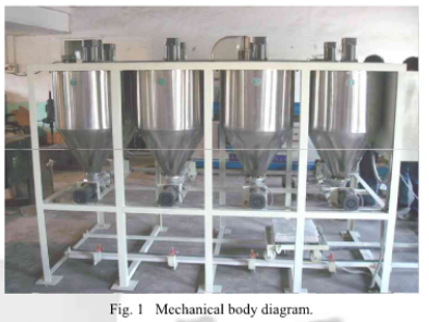
A.System mechanical body
The batching machine is composed by 3 parts-the rack,the store hopper and the weighing hopper. Each store hopper fixed above the rack stores one material. Below the store hopper, belt conveyor is installed and the material in the hopper is made deliver to the weighing hopper through the electrical machinery dragging transportation leather belt.
Weighing hopper hangs in the middle of the beam frame and its bottom is also equipped with a belt conveyor to output material. The system mechanical body is shown in Fig. I.
B. Overall system control scheme
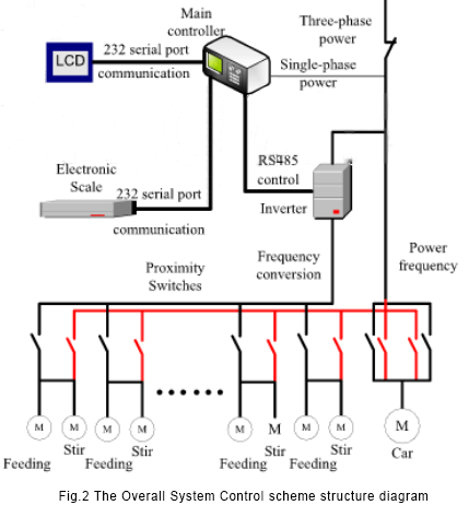
The small automatic batching control system takes integrated mixed-signal SOC C8051F040 as a core, and expands data storage, communications interface, power drive, optical isolation chip. Together with the software and electrical circuit, the system can realize automatic ingredient of powdery material. The system has automatic control and manual control modes. The overall control scheme is shown in Fig.2.
C. Working methods and working principle of automatic
In automatic mode, the system controlled by the controller has three states:run, inquiry and standby state.
When power on, the system waits. When people press the inquiry button, the system is in the state of data query for the formula: when people press the run button, the system runs and ingredients automatically according to specified formula.The automatic patterns work principle is as follows: when the system works, first people set formula and the formula parameter through the keyboard, then the data is saved to the formula memory. After people start the system, controller C8051F040 gets data from electronic scales RS232C serial interfaces, and processes the input signal to obtain the weight of materials. Then it sends data to LCD to display. On the other hand, after weight of materials are compared with the data that stored in memory, it gets the corresponding deviation, then outputs control signal according to established control strategy. Control signal is sent to the inverter after being isolated and droved by optoelectronic devices. Inverter drives motor and adjusts amount of the things by frequency modulation in order to get the best accuracy. At the same time blender works to mix things while the material is being given. There will be alarm and LCD displays when the system fails to work or has unusual ingredients.
D. Manual work and the working principle
When system is in manual state, the automatic control system powers off and it can not automatically ingredients, but the manual control for these separate feeders and mixers is feasible. The feeder and blender will work while the button is being pressed. The operating mode of car movement is the same, and its work model has transferred and the reverse modes.
Before manual batching, the car should be manually placed under the hopper that will be used to batch through reversible buttons. When they are in right position, you can operate them manually. In the process of ingredient, the scale should be manually peeled, and then the feeder material will be feeded until a standard value is reached, and then manually start the car or the feeder to the next bucket of ingredients. The process will repeat until the whole formula finishes.
III HARDWARE DESIGNS OF AUTOMATIC BATCHING CONTROL SYSTEM
A. Main controller design
Small automatic batching control system is widely applied to batching process of chemicals, plastics, food, feed, rubber and tire industry. In conditions of bad scene environment, grid voltage fluctuation, long production lines and complicated control process, this requires the main controller of control system not only addresses control needs interface type and port number but also has high stability and anti-interference. According to design requirements and cost considerations, we finally adopt C8051F chip as a core controller. It has anti-interference ability, lower costs, with two hardware serial ports, two 12-bit DAC converters, 64 digital input/output ports and meets the system needs completely.
The design key is carrying on the system resources disposition including the cross-switches enable configuration, the pin output mode disposition and the pin assignment of external memory interface
a) I/O port configuration: Each pin of C8051F040 can be defined as universal port I/O pin and also be assigned to a digital device. The option of this is realized by Cross-switching priority decoder, We configure UART0 and UARTI to P0.0, P0.1 and P0.2, P0.3, all pin that do not distributed by cross switch can be as universal IO pin. Since the system has 8 feeding trough, in the design, P3, P4 ports are assigned for input ports of 26 signal including the pressed key signal, the inverter breakdown signal, and the proximity switch signal etc.; P5, P6, P7 ports are assigned for output ports of 14 control signal including the inverter control signal, the warning control signal, the movement control signal, the breakdown control signal, 2 car motor control signal, 8 feed motor, the blender control signal and so on.
b) port pin output mode configuration: Each port pin output mode can be configured to drain open-circuit or push-pull method. In Push-pull way, writing logic “0” to corresponding bits of data port register will enable the port pin driven to GND and writing logic “1” will enable the port pin driven to VDD. In the drain open-circuit way, to writing logic “0” to corresponding bits of data port register will enable the port pin driven to GND, writing logic '1' will enable the port pins in a state of high resistance. When the system port pin shared connection of different components, using drain road way can prevent contention between different devices. 0-3 port pins output mode is decided by the corresponding bit of PnMDOUT register. Port pins connected to the SDA, SCL, RX0, RX1 are always configured as open-drain output and have nothing to do with the corresponding bit of PNMDOUT register. In design, P0.0and P0.2 will be separately connected with MAX232 and RS485 interface chip AN65LBC184 in order to achieve communication and control functions; two pins- P1.0 and P1.1 that are used to simulate I2C bus are connected with SDA and SCL pins of non-volatile memory chip AT24C02. So output ports of P0.0, P0.2, P1.0 and P1.1 are configured to drain open-circuit output and the rest of output ports are configured to use the way of push-pull output.
B. Feeding motor drive design
Because the project requires a high precision weighing of materials, the way to ingredient with motor under industrial frequency is difficult to meet product requirements. We control the motor with inverter. Further more, it is also very useful in the longer term, because of frequency conversion technology saving energy. To achieve good control of the motor control system uses Delta Company’s high- performance, low noise VFD-M inverter. It has the character of small size, low-speed torque, improved performance, the strong whole anti-jamming capability and so on.
The output frequency’s way of main controller control inverter includes: analogue voltage control, analog current control and RS485 control. Using RS485 communication interface to control the drag of the AC motor is a low-cost connectivity options. It can greatly decrease the complexity of linear connection and avoid scene all possible electromagnetic interference. In this paper, we transfer RS485 interface chip AN65LBC184 through the monolithic integrated chip serial port to realize control of Delta VFD-M inverter embedded RS485 interface, including inverter’s start, stop, failure detection, breakdown replacement, speed and so on. Its control mode’s schematic diagram is shown in Fig.3.
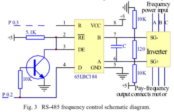
In Fig.3, P0.2 and P0.3 are not directly connected with the converter, but the signal through optical isolation and amplification processing, connects with the inverter. The figure expresses control relationship only.
TV. THE SOFTWARE DESIGN OF AUTOMATIC BATCHING CONTROL SYSTEM
The system program mainly completes to the automatic control of equipment ingredient process, data acquisition, communication, and the automatic alarm in unusual circumstances and so on. This systems software is developed in Keil C51 under the uVcision2 integrated development environment. The programming is flexible and convenient. The software uses the modular programming structure and the entire software divides into the following several parts:
Main program defines the global variable, C8051F040 initialization, data processing, data storage and control of processes.
Keyboard disposal program realizes the state transition of standby, inquiry and run under the automatic control pattern.
Communication program realizes communication of the chip, the electronic scale and liquid-crystal display.
Inverter control program realizes specifically control of the inverter start, stop and the output frequency.
Systems operation's flow chart is shown in Figure 4.
V. CONCLUSION
In this paper, chip C8051F040 is taken as the core controller,and the small automatic batching control system that has automatic and manual modes has been designed. Experiments show that the economical system has high weighing precision, quick speed, stable property, reliable movement, and good market prospect.
REFERENCES
1. Zhou Jianhong, The research of automatic batching control system,
Industry and Mine Automation, 2003, pp 27-28
2. Guo Qihong. Zhang Xianming. The research and design of automatic
batching control system, Electric Drive. 1997, (6): 33-35.
3.USING THE C805IFXXX IN 5 VOLT SYSTEMS, www.xhl.com.cn
NOTICE: This site is reproduced by the editor of this website. The purpose of the reprint is to transmit more information. It does not mean that this website agrees with its views and is responsible for its authenticity. If you are involved in the content, copyright and other issues, please contact us within 30 days, we will delete the content in the first time! [Declaration] The copyright of this article belongs to the original author. The content is the author's personal opinion. This site is only for reference and does not constitute any investment and application advice. This site has the final interpretation of this statement.
Contact: Celia
Phone: +86-13825212800
Tel: +86-13825212800
Email: sales3@meterforall.com
Add: Floor 6 ,Building 11,Longbi Industrial zone, Bantian Street, Longgang District, Shenzhen, China
 zhuohesales3